1. About IGBT losses
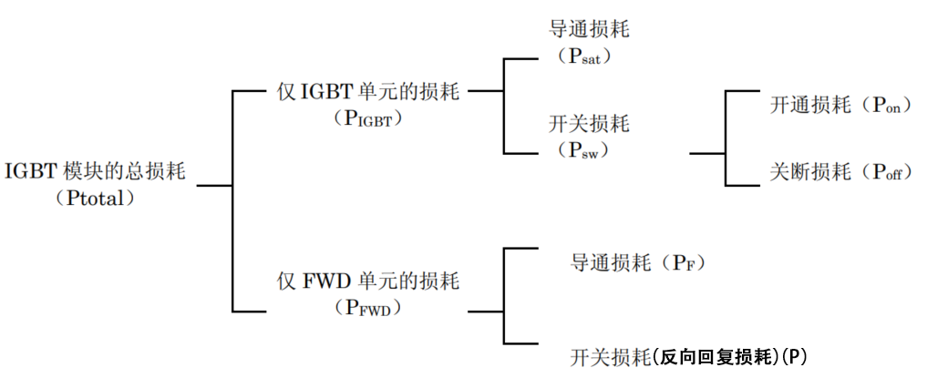
The IGBT module consists of the IGBT unit and the FWD unit, and the sum of the losses generated by each of them is the loss generated by the IGBT module as a whole. In addition, the losses can be generally categorized into conduction losses and switching losses, which are further subdivided as shown below.
The total loss composition of IGBT:
The conduction loss of both the IGBT unit and the FWD unit can be calculated from the output characteristics. At the same time, the switching loss can be calculated from the switching loss-collector current characteristic. The thermal design is based on the calculated losses to ensure that the junction temperature Tj does not exceed the allowable value.
Therefore, the value of the on-state voltage and switching losses at high junction temperatures is usually used for the calculation of losses.
2. DC Chopper Circuit IGBT Loss Calculation Methods
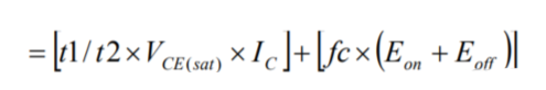
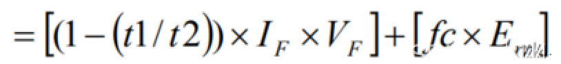
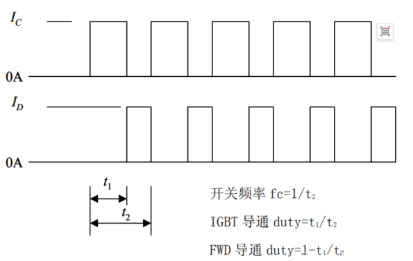
When a DC chopper circuit is in operation, the current flowing in the IGBT or FWD can be thought of as a continuous rectangular wave, which makes it simple to perform an approximate calculation. An approximate DC chopper circuit operating waveform is shown in the figure. The saturation voltage drop and switching loss when the collector current is IC are VCE(sat), Eon, Eoff, respectively, and the on-state voltage and reverse recovery loss when the forward current of the FWD is IF are VF, Err, respectively, and the approximation of the loss of the IGBT module is as follows:
IGBT Losses (W) = Conduction Losses + Turn-On Losses + Turn-Off Losses :
FWD loss (W) = conduction loss + reverse recovery loss
Operating waveform of a DC chopper circuit:
Target Markets and Applications
Conditions such as the actual DC supply voltage and gate resistance value may differ from those recorded in the specifications, in which case approximate calculations can be made according to the following rules.
① When the DC supply voltage Ed(VCC) is different
On-state voltage: not affected by Ed(VCC);
Switching loss: proportional to Ed(VCC);
②When gate resistance value is different
On-state voltage: not affected by gate resistance value;
Switching loss: proportional to switching time, depending on the size of gate resistance value
3. sinusoidal VVVF inverter application of IGBT module loss calculation method
*VVVF, is the abbreviation of Variable Voltage and Variable Frequency, meaning: Variable Voltage, Variable Frequency, which is also known as variable frequency speed control system. VVVF controlled inverter connected to the motor, by changing the frequency and voltage at the same time, to achieve constant magnetic flux (can be approximated by the counterpotential/frequency characterization) and control the motor speed (and the frequency is proportional to the speed) of the purpose, so more often used in frequency converters, belongs to the field of industrial automation.
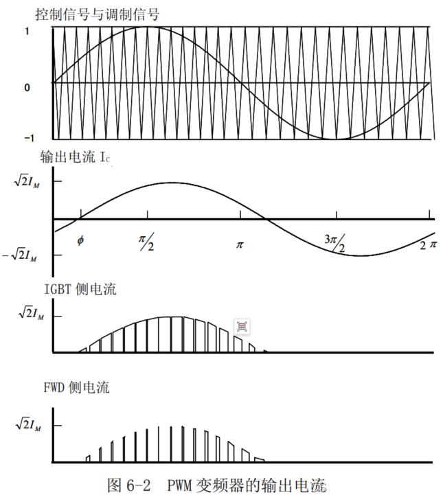
In the case of PWM control by a VVVF inverter or the like, as shown in Fig. 6-2, detailed calculation of losses requires the use of computer simulation techniques or the like because the current value and the state of operation are always changing. However, since the calculation method is too complicated, we introduce a method of shortening the calculation using an approximate formula.